
Objective
This project finds utility in basic signaling setups. For instance, it could be applied in an easier and basic lighting system.
Components (Things You will need)
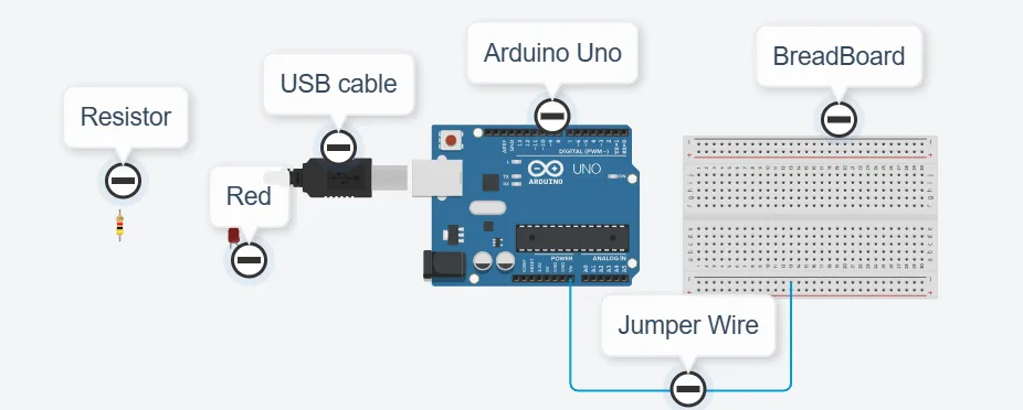 |
||||
|---|---|---|---|---|
Building the circuit
Things Needed:
- Arduino Uno = 1
- Arduino USB cable = 1
- Red LED = 1
- Red jumper wires = 1
- Blue jumper wires = 1
- Resistor =1
Mounting the component on the breadboard
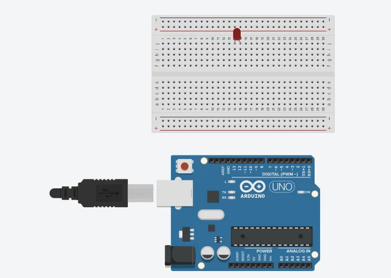
Step 1: Take the breadboard, the RED LED and insert it into the vertical connectors on the breadboard.
 .
.
NB: Make sure you identify where the positive pin (+) and the negative pin (-) is connected to on the breadboard. The longer pin of the LED is the positive pin and the shorter one, the negative PIN.
WIRING THE CIRCUIT
Things Needed:
- Red male-to-male jumper wires = 1
- Blue male-to-male jumper wires = 1
Step 2: Connect one end of red male-to-male jumper wire to the positive pin of the white LED on the breadboard and the other end to hole number 6 on the Arduino UNO.
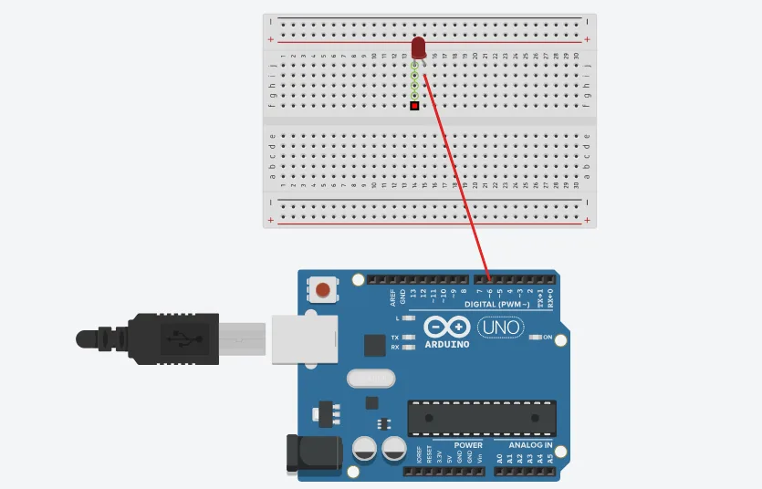
Step 3: Connect one end of the blue male-to-male jumper to the negative pin of the white LED on the breadboard and the other end to GND on the Arduino UNO. Connect a resistor to the negative of the led on the breadboard.
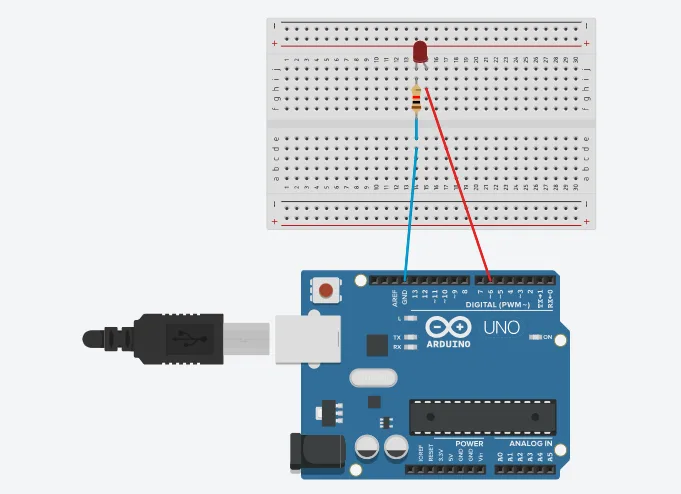 .
.
make sure you connect the arduino usb use blue cable to the Arduino board.
PROGRAMMING
Step 1: Open your Arduino IDE.
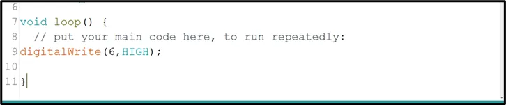
Step 2: Type pinMode (6, OUTPUT);

Step 3: Type digitalWrite (6, HIGH);
 .
.
CONCLUSION
In summary, this LED project presents a basic yet significant step in understanding parallel LED control. By simultaneously lighting up one LED, learners gain insight into simple circuit connections and programming synchronization. This project serves as a starting point for more complex configurations while highlighting the fundamental principle of coordinated electronic actions, setting the stage for broader exploration in electronics and automation.