
Objective
You will learn how to create a simple circuit using a microcontroller, LED and an ultrasonic sensor.
Components (Things You will need)
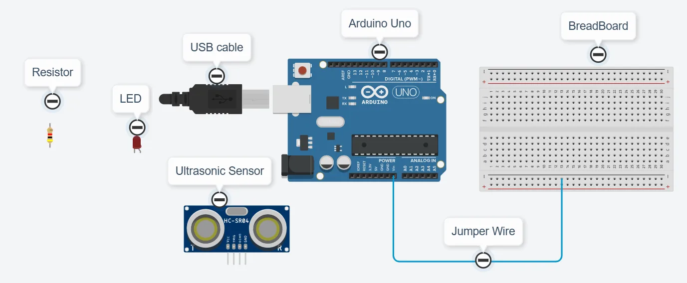
Building the circuit
Things Needed:
- Arduino Uno Board: 1
- Arduino USB cable: 1
- Breadboard: 1
- Red jumper wire: 1
- Black jumper wire: 1
- White jumper wire: 1
- Blue jumper wire: 1
- Brown jumper wire: 1
- Red LED: 1
- Green Jumper Wire: 1
Mounting the component on the breadboard
Things needed:
- Ultrasonic Sensor = 1
- Breadboard =1
- Red LED = 1
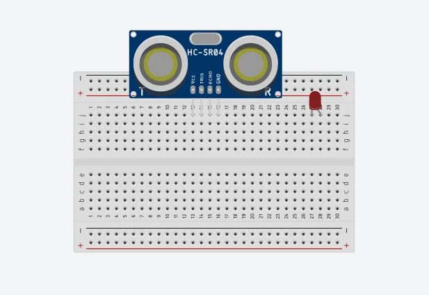
Step 1: Take the breadboard and the ultrasonic sensor. Insert the ultrasonic sensor into the horizontal connectors on the breadboard, with the pins facing outwards as shown in the picture below
WIRING THE CIRCUIT
Things Needed:
- Red male-to-male jumper wire: 1
- Black male-to-male jumper wire: 1
- White male-to-male jumper wire: 1
- Blue male-to-male jumper wire: 1
- Brown jumper wire: 1
- Green Jumper Wire: 1
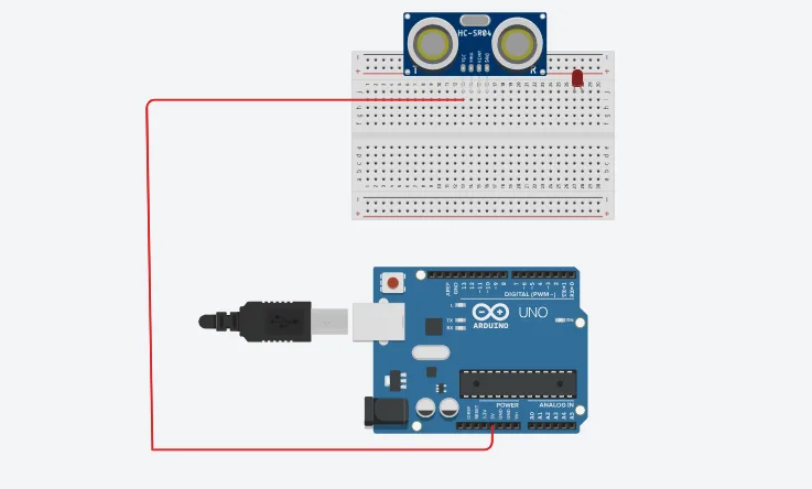
Step 1: Connect one end of the red male-to-male jumper wire to the VCC pin of the Ultrasonic sensor and the other end to the 5V pin on the Arduino Uno board as shown in the picture below.
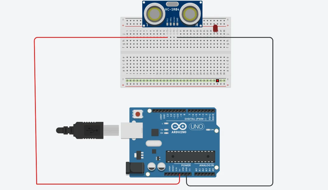
Step 2: Connect one end of the black male-to-male jumper wire to the GND pin of the Ultrasonic sensor and the other end to the GND pin on the Arduino Uno board as shown in the picture below.
Step 3: Connect one end of the white male-to-male jumper wire to the Trig pin of the Ultrasonic sensor and the other end to digital pin 11 on the Arduino Uno board as shown in the picture below.

Step 4: Connect one end of the blue male-to-male jumper wire to the Echo pin of the Ultrasonic sensor and the other end to digital pin 12 on the Arduino Uno board as shown in the picture below.

Step 5: Connect one end of the green male-to-male jumper wire to the positive pin of the LED and the other end to digital pin 13 on the Arduino Uno board as shown in the picture below.

Step 6: Connect one end of the brown male-to-male jumper wire to the negative pin of the LED and the other end to the GND pin on the Arduino Uno board as shown in the picture below.

PROGRAMMING
Step 1: Open your Arduino IDE.
Step 2: const int Echo = 12; to define the Echo pin.
Step 3: Type const int Trig = 11; to define the Trig pin.
Step 4: Press ENTER to go to the next line, type const int led = 13; to define the pin for the led
Step 5: Type long duration; to declare the duration variable.
Step 6: Type int distance; to declare the distance variable.
Step 7: Type const int distance_threshold = 20; to declare the distance threshold variable.
Step 8: Inside the curly brackets of the void setup () function, type pinMode(Trig, OUTPUT); to set the Trig pin as an output.
Step 9: Type pinMode(Echo, INPUT); to set the Echo pin as an input.
Step 10: Type Serial.begin (9600); As shown in the picture below. This is to activate the serial monitor.
Step 11: Type pinMode(led, OUTPUT); As shown in the picture below. This is to activate the serial monitor.
Step 12: Inside the curly brackets of the void loop (), which is where you put your code to run repeatedly. Type digitalWrite(Trig, LOW); As shown in the picture below.
Step 13: Type delay (200); to introduce a delay.
Step 14: Type the following code as shown in the picture below to turn ON the ultrasonic sensor.
digitalWrite(Trig, HIGH);
delay (100); to introduce a delay
Step 15: Type digitalWrite (Trig, LOW); to turn off the ultrasonic sensor. As shown in the picture below to turn OFF the ultrasonic sensor
Step 16: Type the following code
duration = pulseIn (Echo, HIGH); // to read the duration from the Echo pin. As shown in the picture below.
//This is to take input from the Echo pin.

distance = duration * 0.034 / 2; // to calculate the distance. As shown in the picture below.
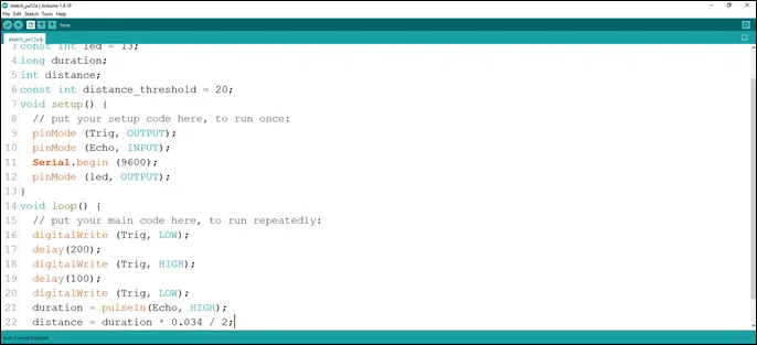
Step 17: Type the conditional statement to turn on the LED at a distance less than the threshold distance.
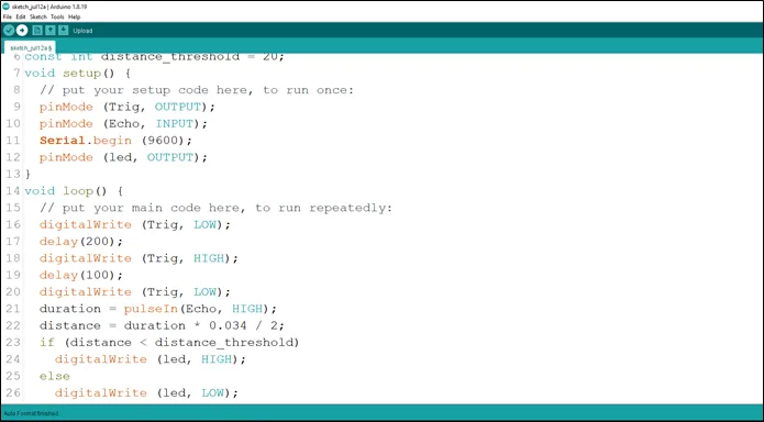 .
.
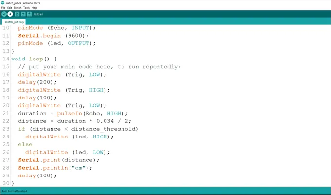
Step 18: Type the following code to print the distance value to the serial monitor. As shown in the picture below.
Serial.print (distance); //This code allows the serial monitor to print the values for distance.
Serial.println (“cm”); //Here a unit is given to the distance values.
delay (100);
 .
.
Step 19: Save your code.
Step 20: Select the arduino board and port.
Step 21: Upload your code.
CONCLUSION
To sum up, the one LED blink project demonstrates a foundational concept in electronics and programming. Through this simple yet illuminating endeavor, learners grasp the essentials of hardware interfacing, coding logic, and timing control. This project lays the groundwork for more advanced explorations while showcasing the transformative power of just a single LED, sparking curiosity and creativity in the world of DIY electronics.